
In this article I want to cover an alternative I’ve come across while building the “real” word clock project. This version will not feature a 12×12 LED-Matrix display. Instead it’s made with LED strips and only the significant words on the clock can light up. With this method you can’t display custom messages, but the whole build won’t cost you as much either. Read all about this build in this article or watch this video:
Necessary components
For the case you’ll need the following items. You should be able to get most of these components in your local hardware store:
| Name | Details | Price |
| Acryl/Glass front panel | 270×270 [mm] | ~5€ (Acryl) |
| Lasercut watch–face | 1,5mm black matte cardboard | ~30€ (incl. shipping) |
| Wood | 2x 300x80x15 [mm] 2x 270x80x15 [mm] 2x 270x40x10 [mm] 2x 250x40x10 [mm] |
~10€ |
| Plywood panels | 2x 270x270x5 [mm] | ~1€ |
| Foam | Will be used as a spacer and to make up a grid for the words on the clock, so the light doesn’t bleed through to other letters that are not meant to be illuminated. | ~5€ |
For the electronics you’ll need:
| Name | Details | Price |
| LED strip with WS2812B or similar integrated controller | 1 meter (60 LEDs) | ~18€ |
| 330 ohm resistor (or something close to it, just for short-circuit protection) | 1 piece | ~0,20€ |
| DC-Jack | 1 piece | ~1,20€ |
| RTC Module | 1 piece | ~2€ |
Important!
You can use any LED-strip you want, as long as the LEDs can be addressed separately or you build your own controller, that switches on the separate segments.
I’ve compiled a list with similar LED-strip controllers. You can download it here.
You’ll also need some kind of microcontroller, to control the LED strip, I used an Arduino Nano in my clock.
Additional materials:
| Name | Details | Price |
| Glue | For wood | ~2€ |
| Glue for the glass plate and foam | I just used some generic all-purpose glue, worked fine | ~2€ |
| Sandpaper | Sand down the surfaces before applying the glue for a better result. | ~1€ |
| Metal brackets | 4 pieces
For hanging the clock on the wall. |
~2€ |
This build is only the bare minimum, it can only display a time that has to be set manually and can’t be changed during operation. If you want to add extra features, you’ll have to change the firmware and build according to your needs.
Downloads
Firmware
Includes test scripts for testing LED functionality and the firmware itself. Updated the firmware. Now it wraps correctly around 12pm/1am and I also added a night-mode where a different color and intensity can be displayed between a pre-defined period (10pm to 6am).
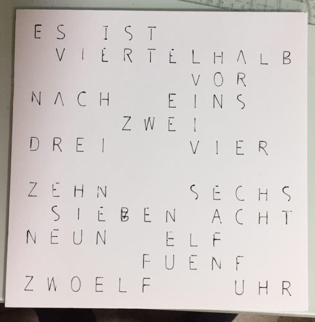
Watchface (German)
You might need to make your own, if you want it in a different language. I included a PSD-file so you only have to change the text and the firmware, so that the correct matrix cells are used.
Assembly instructions
The case
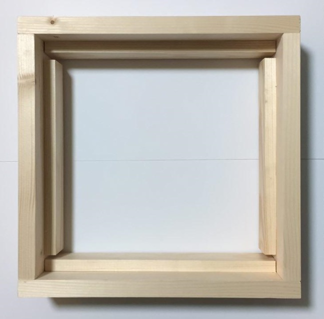
The complete case is made out of two squares and the inner one should fit perfectly into the outer square. Together they form the completed case. The inner one acts as a spacer and mounting place for the LED-boards. Glue the wood pieces together like this:

As you can see in Fig. 1, there should be a 250×250 blank space in the center of the case. This is, where the foam separators will be placed later. I recommend, that you first build the outer shell and then use the front-plate and the watch-face as guides when building the inner frame, so you get a little lip where these two components can be mounted later in the process. This way, they will be flush with the edges of the wooden case and it will look great when finished:

From the back, the case should look like this:
Don’t forget to create a little cut-out for the DC-Jack on any side of the case. I’d recommend the bottom side.
The electronics
This was the part, that took me a long time to do. It was not hard to do, but you’ll have to do all the wiring by hand, so get ready for at least two hours of soldering!
First, take one of the two plywood panels and your front-face and align them, so that the front-face sits on the panel. Afterwards grab a pen and transfer the letters, that you want to light up later, to the plywood panel. It should look like this afterwards:
Now lay out the LED strip on this panel. Try to evenly distribute LEDs over the words. I used all 60 LEDs that came on the strip, but you could use less, if you want to. However, the more you use per word, the better it will look at the end, because all the letters of that one word will light up evenly. Here’s how I distributed them:

When you are happy with the layout, peel off the protective film from the back of the LED-strip and mount the LEDs. Try to place them centered on each word. If your strip is not a self-adhesive one, use some regular glue and let it dry.
Make sure, that you place them in the right direction. My strip had a little arrow on it, indication the way, that the control signal will take:
Align all the strips, so that the arrow always shows in the same direction.
After this is done, you’ll need to drill some 2mm holes. At both sides of each LED-strip drill three holes near to the copper contacts on the strip:

From the back, the mounting-board should look like this:

Now comes the tricky part: You’ll have to connect the LED-strip pieces together, so that they form one long strip again. That means: Connect the LED-strip pieces in each row together (GND -> GND, 5V -> 5V, Data -> Data):

As you can see in Fig. 9, I first connected all the power lines and I made a common +5V and common GND rail on the left and right of the mounting-board. So the strip-pieces are connected together in one line and the last piece of each line is connected to GND on the left and each first piece of a line is connected to +5V.
Afterwards I connected the Data lines of each strip piece of one line together and the last output on a line to the first input of the next line. Then I test-fitted the panel in the case:

I used flexible yellow wires to connect the end of a line with the next one and hard-copper wires to make the connections between the LED-strip pieces, that are on the same line.
Afterwards I tested the connections by running the test-script and when I saw that everything worked, I secured the yellow wires with hot glue, so they don’t fly all over the place in the case and I added a red and black wire for the power rails.
Connect these lines to the DC-Jack and then glue it into place.
Final assembly
When everything works, mount the board with the LEDs in the case, so that the LEDs face forwards. It should look like this:

You can either secure it with screws or just use glue. I settled with the second option, as I don’t plan to remove it again.
After this was done, I started creating the foam-grid that will prevent unwanted letters from lighting up on the front face. So first I cut out eleven 250 x 40 mm pieces out of the foam boards and glued them onto the LED board. Glue these in-between the single lines of text on the front-face:

Now cut the foam into smaller pieces, that go between the lines and place them where necessary. It should look like this:

This way I created single cells for each word, that will light up in the end. After this is done, let everything dry and cut out a 250 x 250 mm piece of parchment-paper or something that’s similar to it. I used it to diffuse the light coming from the LEDs. place it on the foam-grid and secure it with some drops of glue. Try not to place it on the wooden parts.
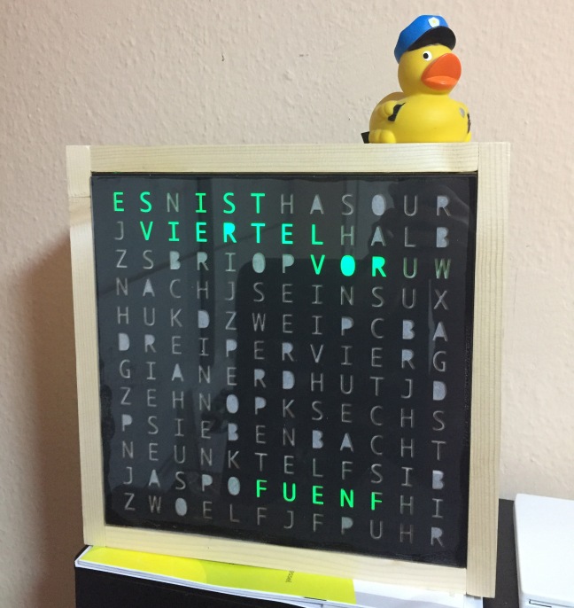
Afterwards glue the laser-cut front face into place and then finish it off with the glass front-face. Remember to remove any protective films. The finished product should look like this:

Now put in all the electronic-components that are left and make the necessary connections. The data-line of the LED-strip is connected to my Arduino on its 2nd pin (pin 2) and I added a 330 Ohm resistor for extra protection. Then connect the RTC-Module to the Arduino’s SDA and SCL pins and to 5V and GND on the Arduino.
The very last step: Screw the metal brackets into place at the back side and drill two holes on the back-cover (the second plywood-panel), so that the clock can be mounted on a wall. Place two of the brackets on the top side and two of them on the bottom side of the clock.
Afterwards close the case up with screws and you’re done!
The firmware
For the firmware I used the fastled and Sodaq-DS3231 libraries for Arduino.
This firmware will only work correctly if you use the same LED-strip controller, as I did. If you want to use a different one, you might need to change the code, so that it fits your parts. I tried to make the code as easy to understand as possible, so you can quickly change it according to your front-face or LED arrangement.
If you only used a different LED-controller, you should be good by only changing this line in the setup()-Method:
FastLED.addLeds<WS2812B, DATA_PIN, RGB>(leds, NUM_LEDS);
However, if you made a different front-plate, change the numbers of the LEDs, that are defined in the beginning of the program. I think the code should be relatively easy to understand and I added comments.
I admit, that the program is not nicely written (everything is hard-coded), and it’s by no means optimized, but I tried to keep is as simple and easy to understand, as possible.
Conclusion
When I started the main word clock build, I wanted to build a cheap one, that everybody could make at home. But this project has become more and more complicated and way too professional (Custom PCBs, lasercut front plate, etc.) and expensive.
With this low-cost alternative I wanted to show you, that it’s still possible to build a cheap word clock at home without any professional tools or materials. Well, OK you’ll still need a laser-cut front-face, but you could do it yourself if you have the patience and time to cut out each letter individually.
The best thing about this is: From the outside, nobody can see how simple it is from the inside, so you can still pretend to be that engineering mastermind, when people come visit your home and even if you don’t plan to do this, you’ll still have a nice way to represent the current time!
Table of contents
The original series:
Part 1 – First steps
Part 2 – The Electronics
Part 2.1 – Quick update and Board Rev. B
Part 3 – The Software
Part 3.1 – Updated Revision
Part 4 – Completing the build (Not released yet)
Addendum:
Part 5 – Low cost variant (You are here)


Hi! We really like this “Homemade DIY word clock – Low cost variant” project and want to feature it on our website. If you are interested, kindly drop me a message on my e-mail: neilmula.eeweb@gmail.com . I’ll be looking forward to your response! Thanks.
LikeLike
Wouldn’t it be possible to make the whole 12×12 grid with a longer LED strip? Maybe there is one, where the LEDs are spaced nicely, so that no cutting is needed.
LikeLiked by 2 people
Yes it would be, and I have to admit, that I should have considered this option, before I started to design my own PCBs …
LikeLiked by 1 person
I have one question: Did you want the letters to look like this? I mean the ‘O’s for example. Theyre missing the inner parts? Because I thinkt it looks nice but that destroys it for me.
LikeLiked by 1 person
At first, I wanted to order a printed sheet of glass, which I did. But the quality was very bad, so I went ahead and bought that laser-cut sheet of cardboard. I didn’t want to change the design, so I simply sent them the first design, which only hat the letters on it and so the company simply did what I told them and they cut out the entire letters with the inner parts (They kindly included each individual letter though). I knew about that, when I ordered it, but I wasn’t sure whether or not I would like it, but I think it turned out looking cool without the inner parts of the letters. I think it gives the whole thing a unique look.
If you want to build this, you can always modify the design and add small supports to each letter individually, so the inner pieces won’t be cut out.
LikeLike
Cool! Such a wonderful clock! Thanks for sharing.
LikeLiked by 1 person
Thanks! I’m glad you liked it 😀
LikeLiked by 1 person