
Introduction
This might not be a common issue, that hobbyists run into when creating their projects, because usually the software PWM, offered by the raspberry pi’s RPi.GPIO-Module, is exact enough for dimming some lights or controlling dc-motors. But for real-time and time-critical applications, this is actually an issue:
The pulses created by the RPi.GPIO Python-Library are not very exact (usually something like +/-100µs):

This happens because of the way software runs on a computer. Without digging too deep into the topic of scheduling and multi-tasking let’s just say: the linux OS on the pi has to give itself and other applications, running on the pi, some time too for processing. So your e.g. Python script, which is doing the PWM work, will just get some time for doing it’s stuff before an other app gets it’s runtime. After an undefined period of time (might even take some ms to seconds) the OS will give your PWM-Program the focus again and it can generate some waveform output. And this is the problem: The time is undefined. It might take 1µs and the pulse gets accurate or it might take 127µs and the pulse is malformed. As mentioned above: This is absolutely no issue when dealing with e.g. LEDs. You won’t notice a difference, because the PWM-Signal is used to generate an average voltage.
Exact timings
But what if you need the signal to be very precise? Let’s say with an inaccuracy of max.
+/- 1µs for e.g. transmitting data? You’ll have to use a hardware generated Signal. Luckily the pi can do this! And with the help of well written high-level libraries you can easily create accurate PWM-Signals with software without having to know anything about the ARM-CPU or about PWM-Registers or about low-level programming. If you want to learn more about the CPU and it’s peripherals anyways, you can read the official documentation: BCM2835-ARM-Peripherals.
After digging a bit into the documentation and after a google search, reading lots of forum posts, i found an easy to use gpio library for the pi. I’ve heard about it before, but I somehow totally forgot about it over the last years. I’m talking about the pigpio library. At this point I want to mention that there are many other good libraries out there, but I liked this the most. Another good one is WiringPi from drogon. He seems to be very active in the Raspberry Pi forums, and the command line tools, that come with WiringPi, are great (you can create pwm-signals from the command-line), but I’ve found the WiringPi-Library to be poorly documented (Not everything, but examples are missing everywhere in the api and also max/min values, etc.). Therefore I decided to use pigpio instead.
I want to re-create the following signal:

As you can see, it is a 22.26kHz rectangular wave with a duty cycle of roughly 59% (If you are not familiar with the term duty cycle or PWM in general, watch this video). After taking a quick look into the pigio API i found this method:
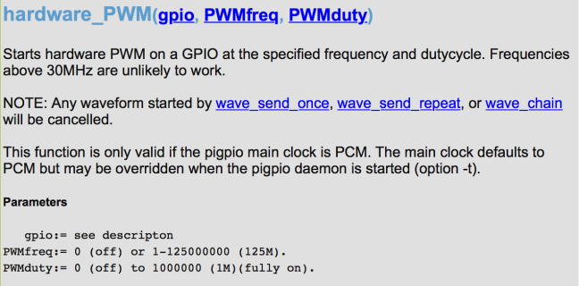
With this method you can create a signal just like the one in Image 2. I’ve quickly written the following lines of code in python:
import pigpio
import time

GPIO = pigpio.pi()

#
# pigpio uses BROADCOM PIN NUMBERING !!!
#

HSYNC = 18 # Physical Pin #12

# Set the GPIO-Mode to ALT5 for HW-PWM
GPIO.set_mode(HSYNC, pigpio.ALT5)

# Start the signal generation
# 22,26kHz, 59% Duty Cycle
GPIO.hardware_PWM(HSYNC, 22260, 590000)

try:
        # Keep the script running until Ctrl + C are pressed
        while True:
                time.sleep(1)
except KeyboardInterrupt:
        pass

# Pull down the GPIO-Pin and cleanup with stop()
GPIO.write(HSYNC, 0)
GPIO.stop()
This script simply uses the pigpio library to create the desired waveform. The infinite while loop is not necessary, but I like to keep the program open and to pull the gpio to zero when ending the script with Ctrl + C. So let’s check, what this script does on the GPIO-Pin:

It looks like I didn’t measure a different signal to the one seen in image 2. The two signals are absolutely the same.
Conclusion
If you need to generate exact pulses (or use a hardware clock signal) with the raspberry pi: It is absolutely possible with low level programming or the use of a good library, but sometimes using the internal clock signals is not precise enough, so be aware of that!


Hi! I’m reading through your blog right now, very informative.
Just thinking, wouldn’t that solve the issue you had with using a Raspberry Pi in your Mac-CRT project?
LikeLiked by 1 person
Before using a BBB to generate the signals for the macdisplay, I tried using a Raspberry Pi, because I already knew that platform. The sync signals could be generated with the Raspberry Pi. However it was not fast and accurate enough to generate and transmit the pixel data, which required a much faster clock and much higher precision. So unfortunately I was unable to use a Pi for the display, even with this precise method.
LikeLike
Hi, very good article! I am looking for a way to send about 60 bytes of data (read from the file) per second through serial port from Raspberry Pi to the microcontroller. Since the rate should be exactly 100 Hz I thought of generating the timing pulses with the µC and polling them with the Raspberry Pi but now that I read you article I wonder if there is a way of doing the opposite – generating the exact 100 Hz timming pulses with the Raspberry Pi followed by sending the data?
LikeLike
Hello! First: thanks, I’m glad you liked the article. Regarding your question: I would say, that this heavily depends on the device, that receives the data from the Pi. You would need to set up a communication protocol, so the two devices know, how to communicate with each other and when to send and expect specific signals. My suggestion is to check, if the receiving end supports SPI, a de-facto standard, when it comes to serial communication between micro-controllers (https://en.wikipedia.org/wiki/Serial_Peripheral_Interface_Bus). This should be quite a bit easier to set up and to test/debug. Even though that would require you to split the 480 Bit of data from your file into small chunks and send them one after the other.
Another alternative, if you would prefer to keep the serial-port or the receiver does not support SPI, is to use UART on the Raspberry-Pi. There are a lot of tutorials around, but here is a nice one, you could use as a starting point: https://www.instructables.com/id/Read-and-write-from-serial-port-with-Raspberry-Pi/
Another aspect to keep in mind is: If you want to read from a file every second, that might also be an issue. Even though, you don’t want to read a lot of data, but the OS on the Pi might not be able to keep up with that rate, but this is just a guess.
Hope that helps!
LikeLike
Thank you very much for the reply! If I understand correctly, by ‘using SPI’ you are suggesting to generate 100 Hz pulses with Raspberry Pi as you described in your article so µC would, upon detecting each synchro pulse, initiate SPI communication to receive the data from the Raspberry Pi? The µC does have SPI (I am using AVR family of microcontrollers) but in that case a µC would be the master and Raspberry Pi would be the slave. As I understand there aren’t reliable libraries for using Raspberry Pi as SPI slave. Instead, I am looking for a way to both generate the sync pulses by Raspberry Pi and to be able to at start some task (communication) in the moment of each synchro pulse. Maybe the PWM output pin could be connected to another input pin with the attached level-change interrupt so Raspberry Pi could trigger itself? It would be even better if there is a way of generatting the interrupt at the start of each pulse generated by PWM library but I am not aware of a way to configure such interrupt service routine without connecting the PWM pin to some other pin configured as input. I’ve successfully used 2 Mbps UART communication with the µC clocked at 16 MHz, why do you thing SPI would be better option? As for the reading the data from the file – the file size is about 1 MB and I will try to load all data into the RAM before starting the process to avoid problems you mentioned that might arise. The main problem is: ‘Is there a way to both generate the 100 Hz pulses and call some function in the moment when each pulse starts?’.
Regards
LikeLike
100 Hz is such a low frequency, that you actually might even be able to generate it very precisely with software, however I have not tested that. But if you have already found out, that UART works, so why go through the trouble of creating a custom communication system? I’d suggest you try and use that, because there are already a lot of reliable libraries around.
Otherwise, if you really want to use a custom clock-signal generated by the Pi, I guess it might work very well with low frequencies, such as 100Hz, however I can not give you a final solution for this problem, simply, because I haven’t tested anything like this before and I don’t want to hand out false information. But I’d say, that with a very low frequency like 100Hz it might even work to generate the pulse (either with wait-commands or like described in the article) and connect the clock-output to another GPIO (like you described in your comment) and simply poll the state of that input-pin and as soon as that changes, put out the next bit of your data (or bits, depending on how many data-lines you want to use). When the microcontroller receives the clock, wait for some time, so that the data-signals can propagate at the Pi’s output(s) and then read it.
However, like I said above, if UART worked for you, I’d absolutely go with that instead!
LikeLike
I don’t think the communication is going to be a problem. I still didn’t test UART communicattion between Rasbperry Pi and the µC using GPIO pins but I tested it with PC + µC + USB –> RS232 adapter @ 2 Mbit/s and with Raspberry Pi + USB –> RS232 adapter + µC at lower speeds – that is why I am assuming Raspberry Pi + µC + GPIO UART would work well. My main concern is generating as accurate 100 Hz timing signal as possible but I am looking for a non-blocking way because I would like to at the same time run some other more processor demanding task (e.g. reproducing .mp3 file). I will try to generate 100 Hz by using the method you described in the article and to configure the interrupt triggered by rising edge of the generated signal. Inside ISR I’ll try to send 60 bytes through UART and the µC should get 60 bytes 100 times per second + ‘the end of transmission’ will serve as the syncro-event.
Thank you very much for your help!
LikeLiked by 1 person
You’re welcome and I’m glad I could help. I can assure you, that generating a precise 100Hz won’t be a problem with either method. Also feel free to share your results regarding the interrupts and how precise that works via the comments on this page. Good luck with the project!
LikeLike
The best solution and explanation for hardware-PWM which i have found after many hours of searching.
Thank you!
But please explain me, what means ALT5 in the example.
LikeLiked by 1 person
Thanks! I’m glad you liked it and it helped you.
ALT5 is simply the mode the GPIO is put into. Some GPIO pins have alternative modes, which you can select with an internal pin multiplexer. In this case, ALT5 is the alternative mode 5, which enables hardware PWM, which makes these precise timings possible. However you can read more about that in the official documentation here:
http://abyz.me.uk/rpi/pigpio/python.html#set_mode
and more about the GPIO multiplexer and alternative modes here:
http://www.dummies.com/computers/raspberry-pi/raspberry-pi-gpio-pin-alternate-functions/
LikeLike
Exactly what I was looking for. Thanks !
LikeLiked by 1 person
You are welcome! I’m glad you liked it 😀
LikeLike
thanks for this quick hint. i want to use this for a distance measurement with a parking sensor module
LikeLiked by 1 person